When discussing metallurgical microscopes, most of the time the conversation will be centred around inverted metallurgical microscopes. And there is the most logical reason why the metallurgical microscope is typically constructed as an inverted microscope?
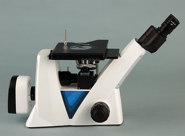
The microscope is inverted because metal samples are large, heavy, and opaque. An inverted design allows you to place the sample on top of the stage, protects the objectives underneath, and enables you to obtain a better reflective-light image without having to dissect the part.
If you deal with metal parts, not just small embedded samples, the inverted design addresses challenges you would encounter daily. Let’s go through these particulars in a straightforward, functional manner.
Why Is the Metallurgical Microscope Usually Designed as an Inverted Microscope?
Metal samples are not like biology slides
Biological microscopes use thin, transparent samples.
Metallurgical samples? They’re the exact opposite:
- Solid metal
- Heavy blocks or irregular parts
- Non-transparent (so you can’t use transmitted light)
- Often large: gears, crankshafts, castings, bearings, molds
- This alone is enough to make upright microscopes inconvenient or impossible.
What advantages does an inverted design bring?
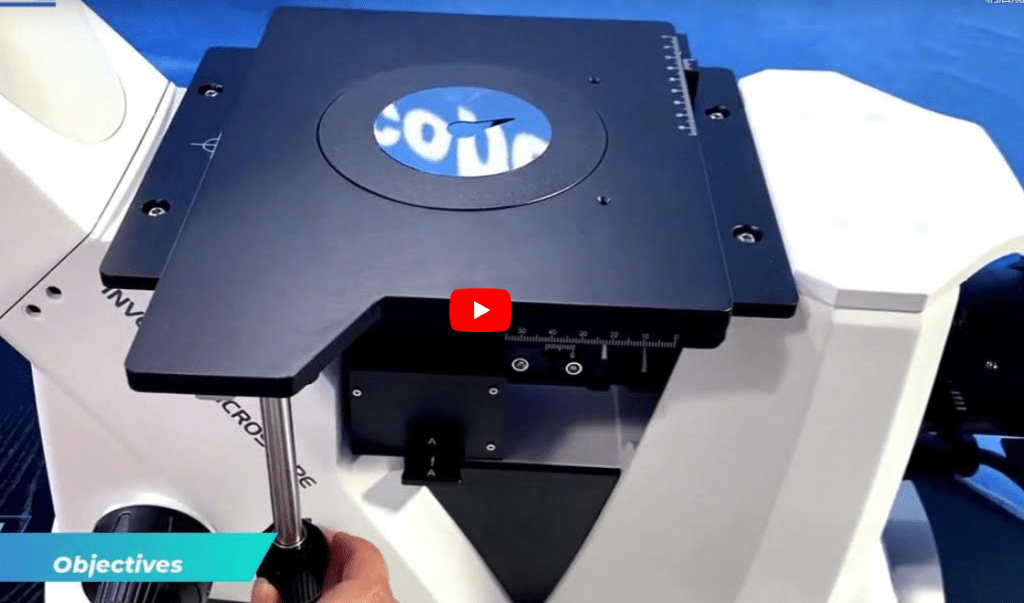
1) You can place big metal samples directly on the stage
No cutting, no embedding, no tricky mounting.
Just polish, etch, and place it down. Done.
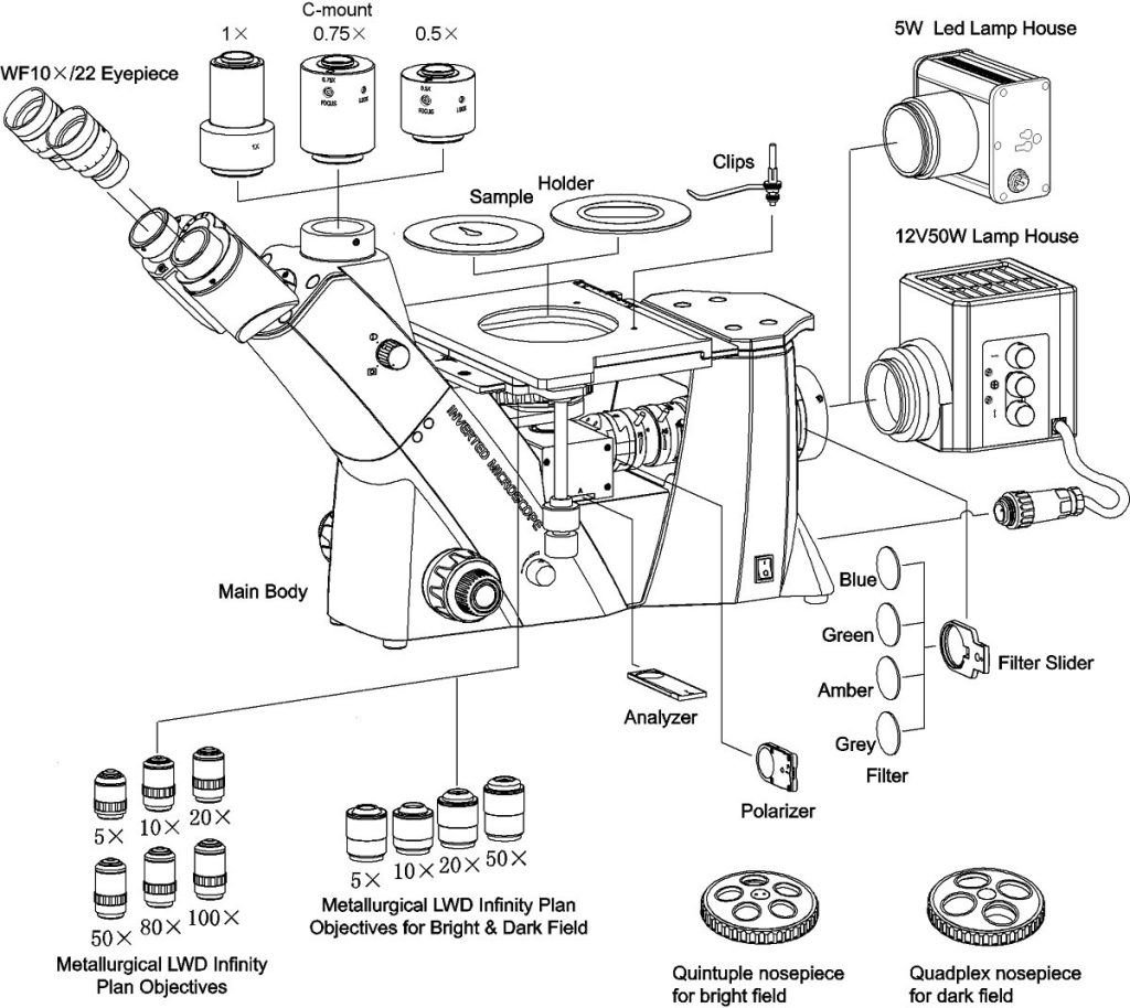
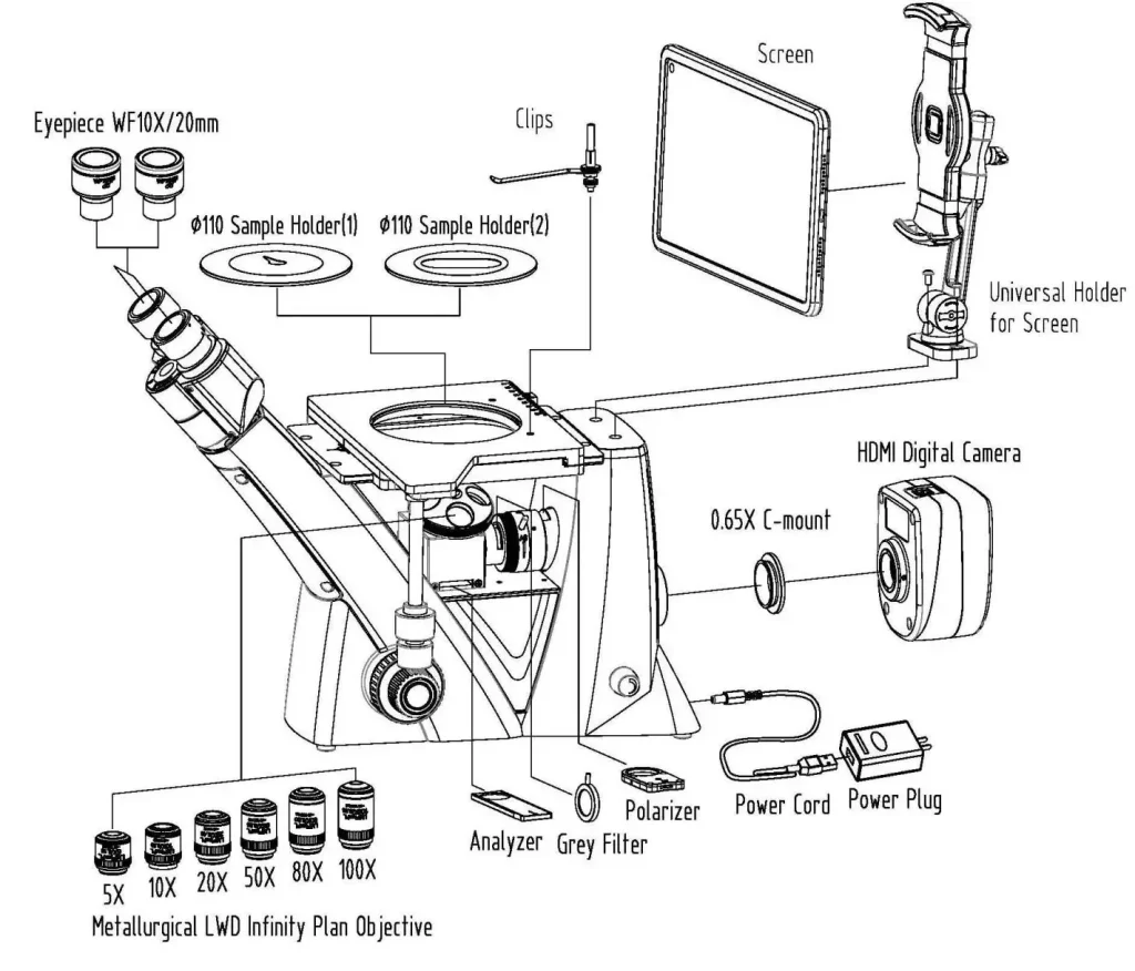
2) The objectives stay safe under the stage
Metal surfaces are hard. One wrong move on an upright scope and the objective gets scratched.
In an inverted microscope, the objective sits underneath—out of harm’s way.
3) Better geometry for reflective-light imaging
Metallurgy relies on reflected light.
An inverted design keeps illumination and imaging perfectly aligned, which gives you:
- cleaner grain boundaries
- stronger phase contrast
- more stable lighting
- fewer artifacts caused by sample height variations
4) You don’t have to cut samples into small blocks
If you’re inspecting a heavy casting or a forged part, you simply cannot “fit” it under an upright microscope.
Inverted solves that instantly.
What real-world problems does it solve?
- If the objectives are damaged, the objectives can be eliminated.
- If the size of the sample is too big, there is no problem with that.
- If the surface is uneven, there are long-working-distance objectives that can handle it.
- If it is too time-consuming to prepare samples, there is a reduced sample prep time.
- If consistent reflected-light quality is of concern, there is better alignment.
For everyday observations in metallography, this functionality can save hours.
How the Inverted Design Works — and Why the Advantages Are So Big
Let’s explain the inverted structure in plain English.
Why does the light path go from bottom to top?
Because metals reflect, not transmit light.
Sending the light upward toward the sample gives:
- a direct reflective signal
- less scattered light
- a stronger, cleaner image
- minimal obstruction from the user’s hands or tools
Why are samples placed on a flat upper stage?
Because metal parts:
- are heavy
- need stable support
- must lie perfectly flat for polished-surface imaging
- Often have uneven shapes that cannot fit under an upright frame
A flat top stage acts like a “workbench”—strong, stable, and idiot-proof.
Why don’t upright microscopes work well for metal samples?
| Limitation | What happens with an upright microscope |
| Sample size | Large parts simply don’t fit into the space below the objective |
| Sample weight | The stage cannot support heavy components |
| Objective safety | High risk of scratching or collision |
| Reflective light | More stray reflections and uneven illumination |
| Practical use | Requires cutting or embedding the sample first |
Upright microscopes work well for small, embedded coupons—not real-world metal components.
Where Inverted Metallurgical Microscopes Are Essential
You’ll find them anywhere where metal integrity and surface structure matter.
Common industrial use cases
- Automotive manufacturing: Gear teeth, crankshafts, camshafts, valve parts
- Aerospace components: Turbine blades, structural alloy parts
- Heat treatment quality control: Case depth, martensite distribution, decarburization
- Casting and forging: Inclusions, porosity, dendrites, grain size
- Failure analysis & forensic engineering: Crack growth, fatigue, corrosion, wear patterns
- Welding inspection: Weld pool microstructure, HAZ, grain refinement
A 10–20 kg component?
An inverted metallurgical microscope is the only design that makes sense.
Upright vs. Inverted Metallurgical Microscopes
| Feature | Inverted Metallurgical Microscope | Upright Metallurgical Microscope |
| Sample position | The sample must fit under the objective | Sample must fit under the objective |
| Objective position | Under the stage → protected | Above the stage → higher collision risk |
| Sample size | Ideal for large, heavy metal parts | For small embedded samples |
| Sample prep | Minimal, often no cutting required | Requires cutting/mounting |
| Light path | Bottom-up reflective illumination | Top-down reflective illumination |
| Best for | Automotive, aerospace, heat treatment, factory QC | Lab-based small specimens |
If your samples are “real-world metal parts,” inverted wins every time.
Summary
So, why are metallurgical microscopes usually inverted? Because the inverted design matches the real-world nature of metal samples: heavy, opaque, reflective, and often large.With bottom-up illumination, protected objectives, and a strong top-stage platform, an inverted metallurgical microscope gives you:
- easier sample handling
- safer operation
- better reflective-light images
- less sample preparation
- broader compatibility with industrial-sized components
If your work involves metal surfaces, heat-treated parts, or industrial failure analysis, choosing an inverted metallurgical microscope isn’t just convenient—it’s the most efficient, accurate, and practical option.